Communications and Networking
Design, build, and connect wired or wireless node(s) with network or bus addresses
Send a message between two projects
Introduction
What is Networking and Communication?
Data communications refers to the transmission of this digital data between two or more computers and a computer network or data network is a telecommunications network that allows computers to exchange data. The physical connection between networked computing devices is established using either cable media or wireless media. The best-known computer network is the Internet.

So in this week I have decided to make a wired network using I2C protocol.
I2C
I choosed I2C communication to do the assignment this week. So what is i2C communication? The Inter-integrated Circuit (I2C) Protocol is a protocol intended to allow multiple slave digital integrated circuits (chips) to communicate with one or more master chips. Like the Serial Peripheral Interface (SPI), it is only intended for short distance communications within a single device. Like Asynchronous Serial Interfaces (such as RS-232 or UARTs), it only requires two signal wires to exchange information. I2C requires a mere two wires, like asynchronous serial, but those two wires can support up to 1008 slave devices. Also, unlike SPI, I2C can support a multi-master system, allowing more than one master to communicate with all devices on the bus (although the master devices can’t talk to each other over the bus and must take turns using the bus lines). Data rates fall between asynchronous serial and SPI most I2C devices can communicate at 100kHz or 400kHz. There is some overhead with I2C for every 8 bits of data to be sent, one extra bit of meta data must be transmitted. The hardware required to implement I2C is more complex than SPI, but less than asynchronous serial. It can be fairly trivially implemented in software.
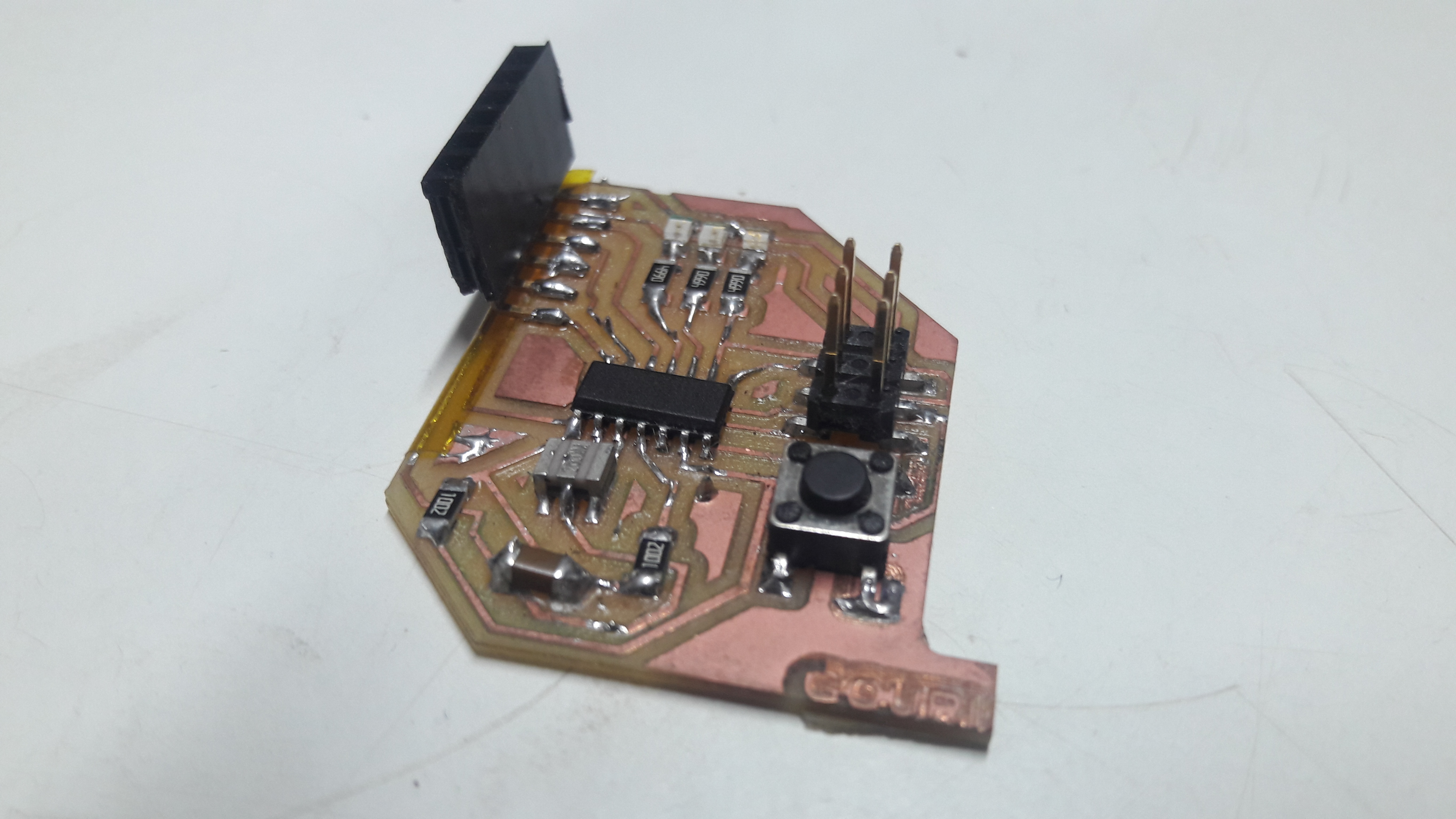
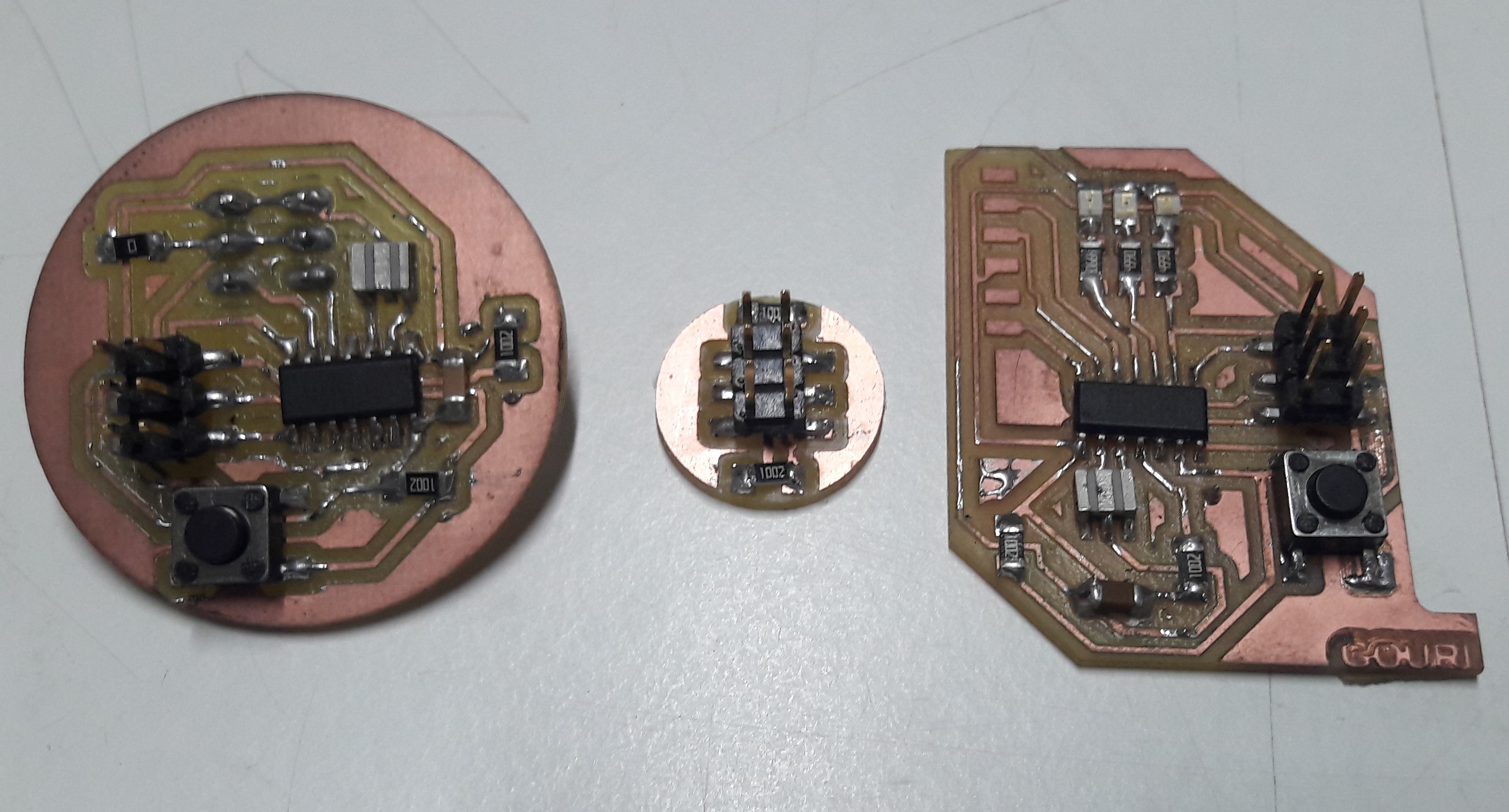
I choosed Attiny44 as the microcontroller. I found ICSP pins MOSI and SCK are I2c pins. So i thought of resuing the Previous Boards, which i used in output week The master board which consist of a Button and slave board made in electronic design week consist of RGB LED . So when i press the button on Master board, the LED on the slave board will glow. So that is my plan. Now lets start coding.I need to make a pullup resistance in I2C. So i designed a board withicsp pin headers and Pullup resistors
Board designing
Designing the pullup board
I designed a pullup board for communication.
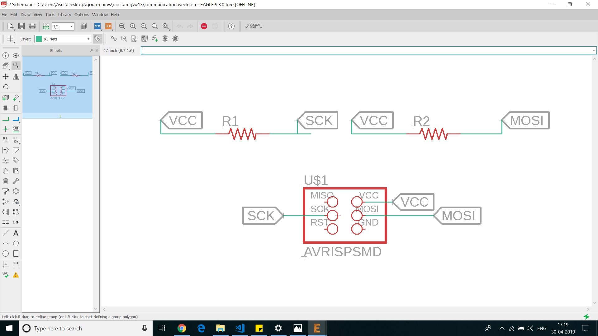
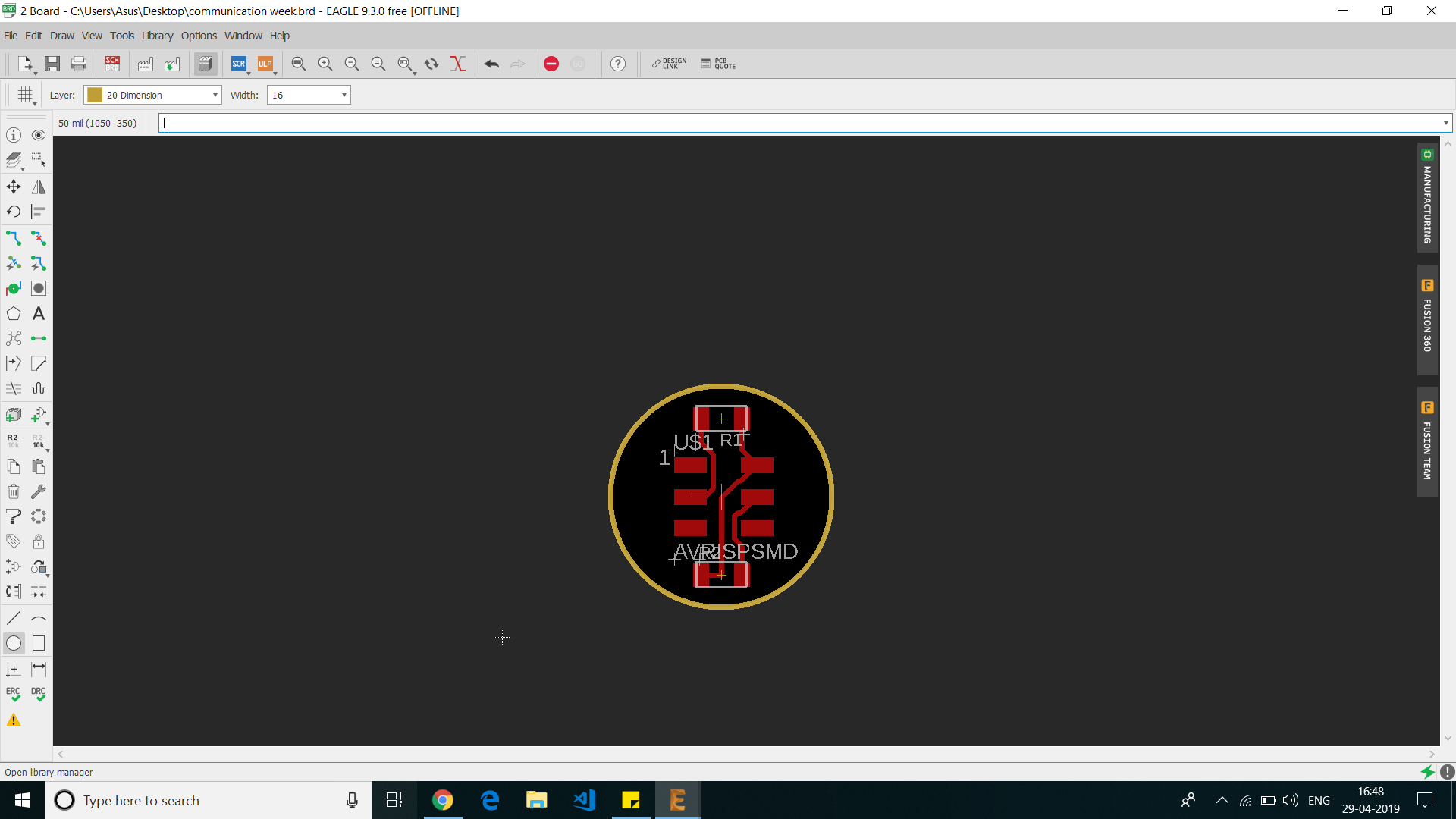
This board is only for pullup, its have 2 resistors. One pullup for both SDA and SCL.
so if we attach this to an i2c chanel, both SDA and SCL channel will be pulled up.
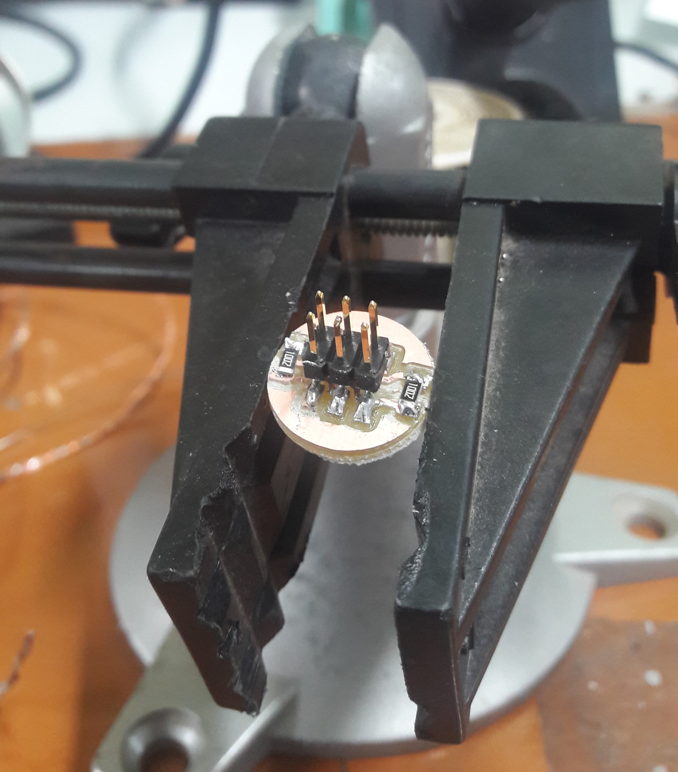
PCB milling and soldering

Now i need to millout the PCB using modella MDX20 PCB milling machine. I used the same steps that i followed on my previous elecronics design weeks.
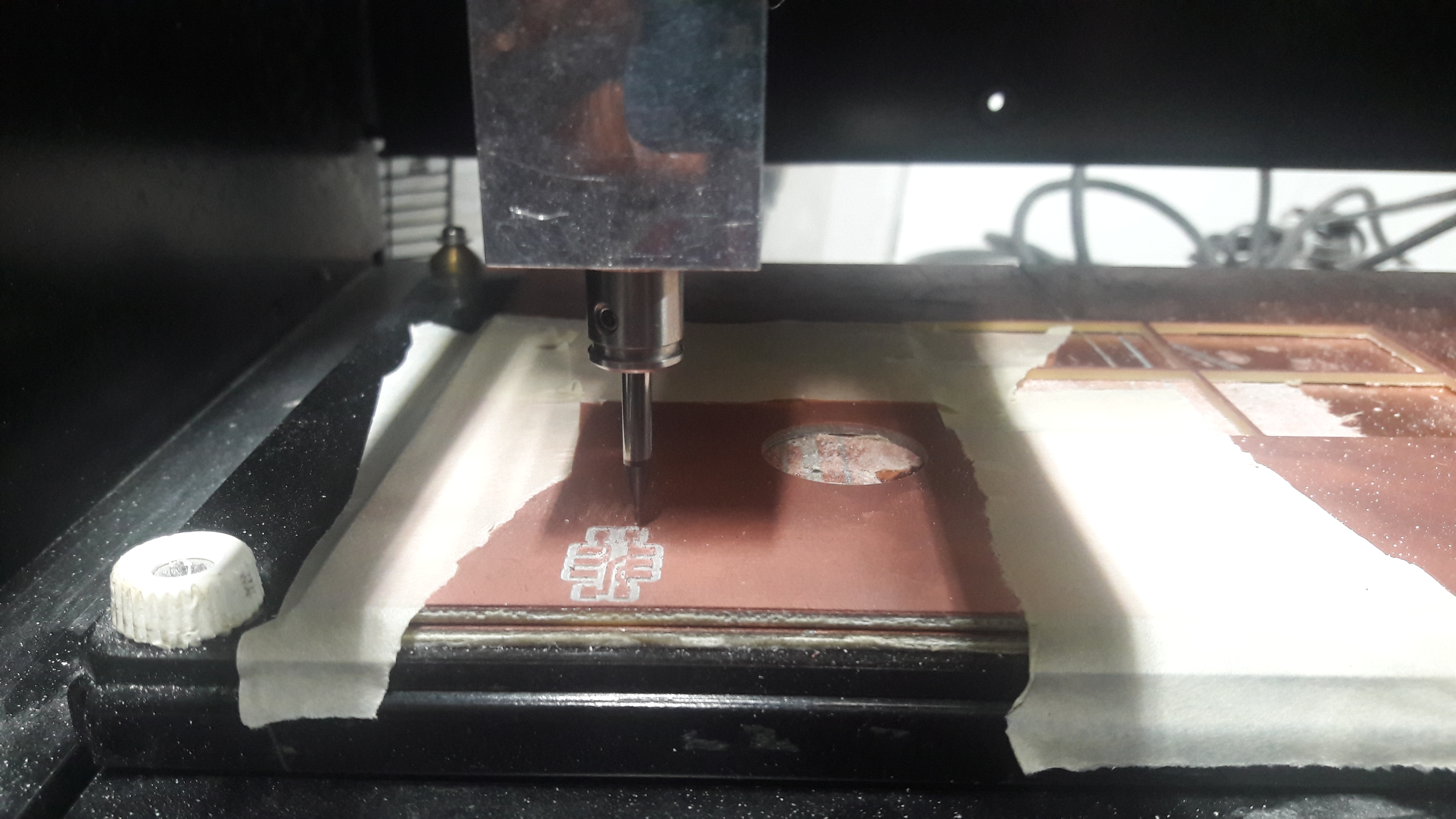
After milling the PCB. i pullout the PCBs from the milling bed. Then i soldered all the components to the boards carefully.
So for I2C networking, I took my previously done boards.
I used my previous output device board has my master board.
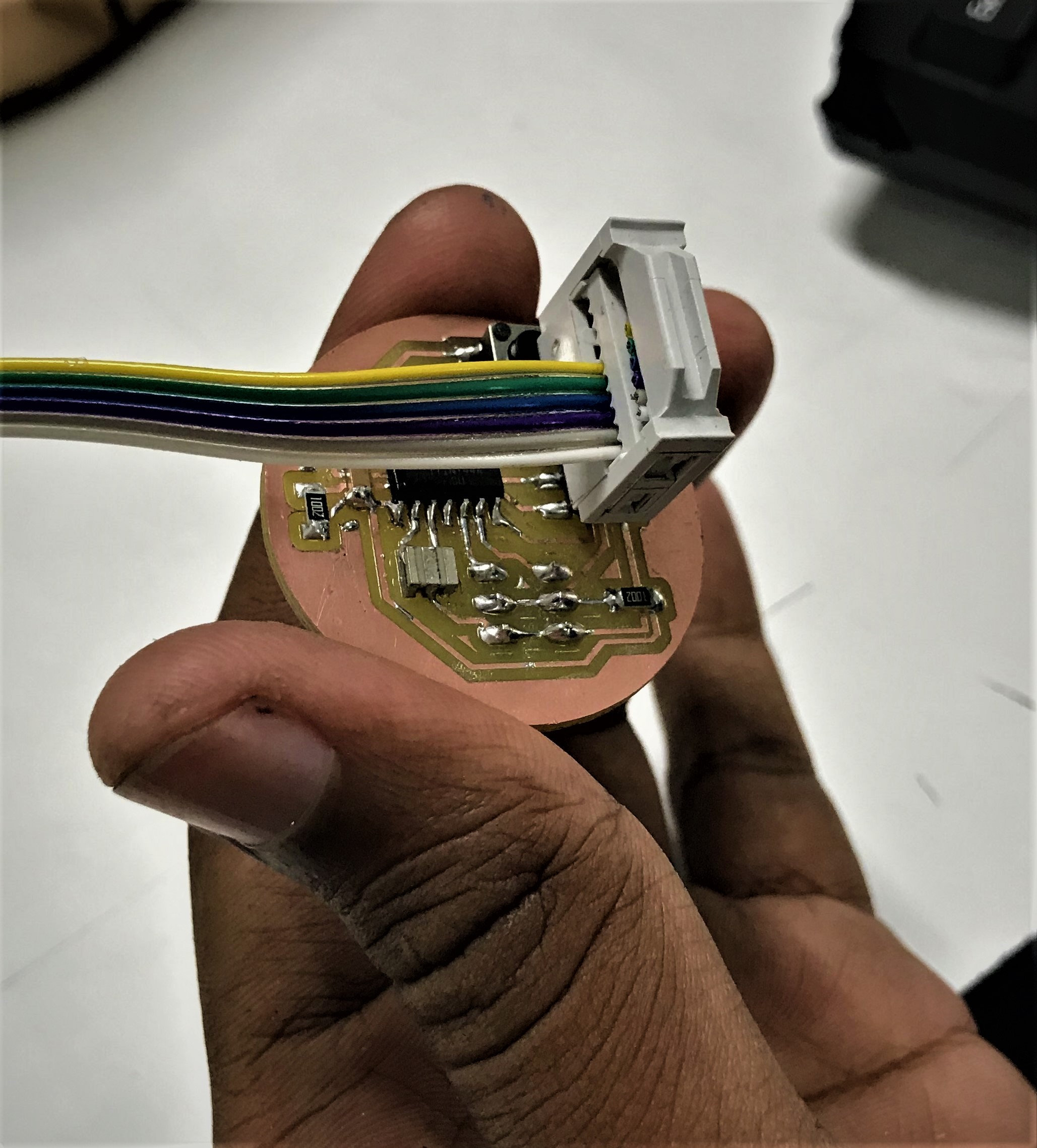
I used my previous electronic design board has my slave board.
You can download the eagle project from here.
Programming the board
Now i need to program each of the boards.I used TinyWire.h library for arduino. The TinyWire.h library is build a for attiny microcontrollers.I have installed the library in my arduino IDE.
Now i need to write the code for the master to turn on the LEDs on the slave board using I2C communication.
Arduino Code for Master
                                                    #include <TinyWireM.h>
                                                    #define device (1)
                                                    #define button 3


                                                    void setup() {
                                                    pinMode(button,INPUT);
                                                    TinyWireM.begin();

                                                    }
                                                    void loop() {

                                                    int val = analogRead(button);
                                                    if(button>0)
                                                    {

                                                    TinyWireM.beginTransmission(device);
                                                    TinyWireM.send(1);
                                                    TinyWireM.endTransmission();

                                                    }
                                                    else
                                                    {TinyWireM.beginTransmission(device);
                                                    TinyWireM.send(0);
                                                    TinyWireM.endTransmission();
                                                    }
                                                    }
You can download the arduino project from here.
Arduino Code for Slave
                                                        #include <TinyWireS.h>
                                                        #define LED1 2
                                                        #define LED2 7
                                                        #define LED3 A2
                                                        #define I2C_SLAVE_ADDR (1)
                                                        byte data = 0;

                                                        void setup() {
                                                          TinyWireS.begin(I2C_SLAVE_ADDR);
                                                          pinMode(LED1, OUTPUT);
                                                          pinMode(LED2, OUTPUT);
                                                          pinMode(LED3, OUTPUT);
                                                        }

                                                        void loop() {
                                                          if (TinyWireS.available())
                                                            data = TinyWireS.receive();
                                                          if (data == 1) {
                                                            digitalWrite(LED1, HIGH);
                                                            digitalWrite(LED2, HIGH);
                                                            digitalWrite(LED3, HIGH);
                                                          }
                                                          else if (data == 0) {
                                                            digitalWrite(LED1, LOW);
                                                            digitalWrite(LED2, LOW);
                                                            digitalWrite(LED3, LOW);
                                                          }
                                                        }
You can download the arduino project from here.
I have made arduino code for both master and slave board but my result was failure.i tried a lot to correct it.we has a team faced problem during the communication week.
After trying individually later my class mate tried editing the library working the program.
First he tried the Wire.h library that official given by the Arduino. But when compailing the wire.h library he got some error. So like he googled a lot and saw some answers from arduino forum that wire.h library wont work with attiny45 microcontrollers.Then he started trying new editings.He searched for alternative arduino libaries that especially build for attiny microcontrollers. Then he found TinyWire.h library for arduino. The TinyWire.h library is build for attiny microcontrollers. The library almost replicate the wire.h but stil some problems were there, so he tried editing library files. He edit some values in library and the program started working with 8MHZ internal crystal.Then he used 20Mhz oscilator in his boards,Then it didnt work for 20 Mhz.The reason was not sure.
Finally i joined my classmate for seeing the result in communication.Still i have problem with my own libraray for completing my work individual work.
